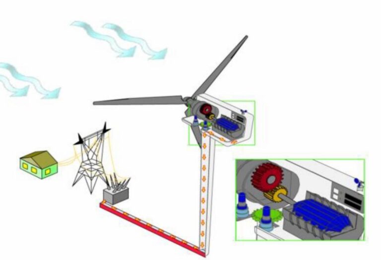
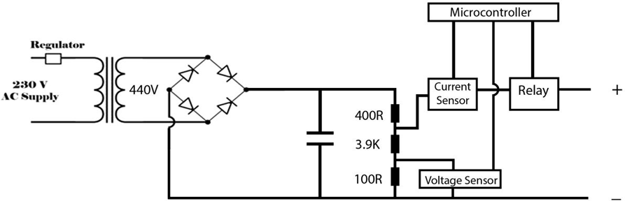
This device is a specific device to check the DC bus line of the VFD (Variable Frequency Drive) and reforming the capacitors in the industries. The module can regulate around 1000V. It has Rectifier Bridge, Step-up transformer, Arduino controller to modify this device.

Main objective of our project is avoiding the problems in DC bus line of the VFD drives and reforming the Capacitors. And also Display the Voltage level and Indicate of a fully charged Capacitor through the Arduino controller.
1. METHODOLOGY
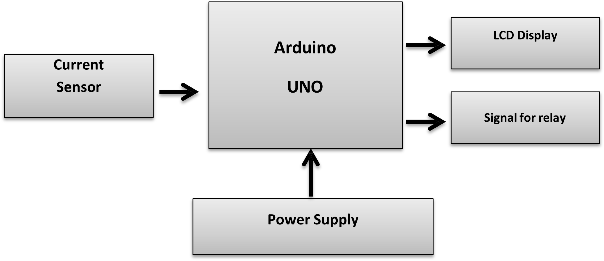
Firstly, hardware section was implemented & components were placed in correct positions in enclosure. Then an Arduino code was designed for the project and the voltage was controlled by the device automatically using Microcontroller.
2. HARDWARE REQUIREMENTS
2.1 Arduino Uno R3
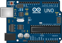
Arduino is a hardware and software company that designs and manufactures single board micro controllers. The Arduino language is merely a set of C/C++ functions that can be called from code.
2.3 Specifications
Microcontroller ATmega328
Operating Voltage 5V
Input Voltage (recommended) 7-12V
Input Voltage (limits) 6-20V
Digital I/O Pins 14 (of which 6 provide PWM output)
Analog Input Pins 6
DC Current per I/O Pin 40 mA
DC Current for 3.3V Pin 50 mA
Flash Memory 32 KB (ATmega328)
SRAM 2 KB (ATmega328)
EEPROM 1 KB (ATmega328)
Clock Speed 16 MHz
The maximum length and width of the Uno PCB are 2.7 and 2.1 inches respectively, with the USB connector and power jack extending beyond the former dimension. Four screw holes allow the board to be attached to a surface or case. Note that the distance between digital pins 7 and 8 is 160 mil (0.16″), not an even multiple of the 100 mil spacing of the other pins.
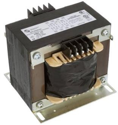
Transformer (230 to 440 AC Step Up)
Amp Current sensor
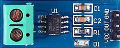
ACS712 is a current sensor that can operate on both AC and DC. This sensor operates at 5V and produces an analog voltage output proportional to the measured current. This tool consists of a series of precision Hall sensors with copper lines.
The output of this instrument has a positive slope when the current increases through the copper primary conduction path (from pins 1 and 2 to pins 3 and 4). The internal resistance of the conduction path is 1.2 mΩ.
This sensor has an output voltage of Vcc x 0.5 = 2.5 at the input current 0A and a 5V Vcc power supply. There are three types based on the readable current range, ± 5A, ± 20A, and ± 30A with output sensitivity of each type of 185mV / A, 100mV / A, and 66mV / A respectively. The output of this current sensor is analog, so to read it, we can directly measure the output voltage using voltmeter or measure it by using a microcontroller like Arduino through Analog Read pin or ADC pin
Voltage Sensor Module
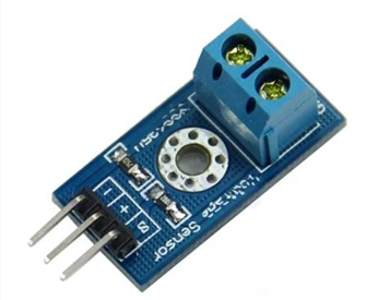
Voltage Sensor is a precise low-cost sensor for measuring voltage. It is based on the principle of resistive voltage divider design. It can make the red terminal connector input voltage to 5 times smaller.
- Input Voltage : 0 to 25V
- Voltage Detection Range : 02445 to 25
- Analog Voltage Resolution : 0.00489V
- Needs no external components
- Easy to use with Microcontrollers
- Small, cheap and easily available
LCD Display
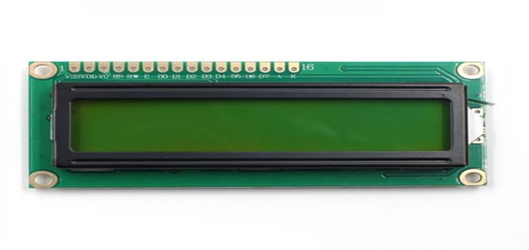
16×2 LCD is named so because; it has 16 Columns and 2 Rows. There are a lot of combinations available like, 8×1, 8×2, 10×2, 16×1, etc. but the most used one is the 16×2 LCD. So, it will have (16×2=32) 32 characters in total and each character will be made of 5×8 Pixel Dots. It requires a supply of 5V.
3. SOFTWARE REQUIREMENTS
Arduino IDE
The Arduino Integrated Development Environment – or Arduino Software (IDE) – contains a text editor for writing code, a message area, a text console, a toolbar with buttons for common functions and a series of menus. It connects to the Arduino and Genuino hardware to upload programs and communicate with them

RESULT
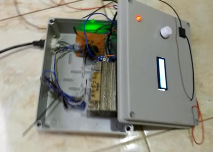
This portable device can be used to reforming capacitors and indicate the charging level of it. All the components were placed in enclosure to provide compact structure. Display unit, indicator and AC voltage regulator were placed on up side of enclosure for better control and view.
4 ARDUINO PROGRAM
4.0 CODING FOR PROJECT
#include <LiquidCrystal.h>
//(RS, E, D4, D5, D6, D7)
LiquidCrystal lcd = LiquidCrystal(4, 5, 6, 7, 8, 9);
const int voltageSensor = A0;
const int currentSensor = A1;
int value;
int m;
int relaypin = 3;
int bypass;
void setup() { Serial.begin(9600); lcd.begin(16, 2);
lcd.setCursor(1, 0);
}
void loop() {
unsigned int x=0;
float AcsValue=0.0,Samples=0.0,AvgAcs=0.0,AcsValueF=0.0;
for (int x = 0; x < 150; x++){
value = analogRead(voltageSensor);
AcsValue = analogRead(A1); //Read current sensor values Samples = Samples + AcsValue;
delay (3); }
AvgAcs=Samples/150.0;
AcsValueF = (2.5 – (AvgAcs * (5.0 / 1024.0)) )/0.066;
bypass = (AcsValueF,DEC);
if (bypass <= 0)
{digitalWrite(relaypin,HIGH);}
else
{digitalWrite(relaypin,LOW);}
Serial.println(AcsValueF);//Print the read current on Serial monitor
delay(50);
}
lcd.clear();
lcd.setCursor(1, 0);
lcd.print(“DC = ” );
m = map(value, 0, 1024, 0, 1000);
lcd.print(m);
lcd.print(“V”);
Serial.println(m);
delay(1000);
4.1 PROBLEMS AND SOLUTION
Here, Transformer out is 440VAC that enough for a dangerous electrical shock. So, proper insulation was added to the project.
Output DC voltage stability and tuning was gained by adding regulator and adjusting it in supply side.
Here, all the resistors were placed in series to provide large value, otherwise output DC voltage may damage the microcontroller and voltage sensor in higher value while tuning.
4.1 ADVANTAGES
Can be maintained a safety distance from the device.
Portable structure.
No need of much knowledge.
4.2 APPLICATIONS
Checking DC bus lines.
Charging the capacitors.
5.0 Conclusion
The module is working on a low ampere to charge the capacitors slowly to reduce the damages.
This module is only made for the VFD services. Especially for the main part of the VFD inverter side and DC bus line. We can start the voltage level from zero to thousand voltages as the requirement of the voltage of the machine. It is a good protecting device.