Earthing Resistance Values: Guidelines for Electrical Engineers
Ensure proper earthing is vital for safety, performance and regulatory compliance in electrical systems.
Here’s an informative breakdown of typical and device-specific earthing resistance values.
🌟 Typical Earthing Resistance Values:-
🔹 Power Transformers: 1-5 ohms
🔹 Generators: 0.5-2 ohms
🔹 Motors: 1-10 ohms
🔹 Switchgear: 0.5-5 ohms
🔹 Control Panels: 1-10 ohms
🔹 Lighting Systems: 1-5 ohms
🔹 Distribution Boards: 1-5 ohms
🔧 Device-Specific Earthing Values:-
🔸 Circuit Breakers: 0.1-1 ohm
🔸 Relays: 0.1-10 ohms
🔸 Magnetic Contactors: 0.1-10 ohms
🔸 Motors (LT/HT): 0.5-5 ohms
🔸 Transformers (Dry/Oil-Filled): 1-10 ohms
🔸 Battery Systems: 0.1-1 ohm
🔸 UPS Systems: 0.1-1 ohm
🏭 Power Plant-Specific Resistance Ranges:-
🌞 Solar Power Plants: 1-5 ohms
🌊 Hydro Power Plants: 1-10 ohms
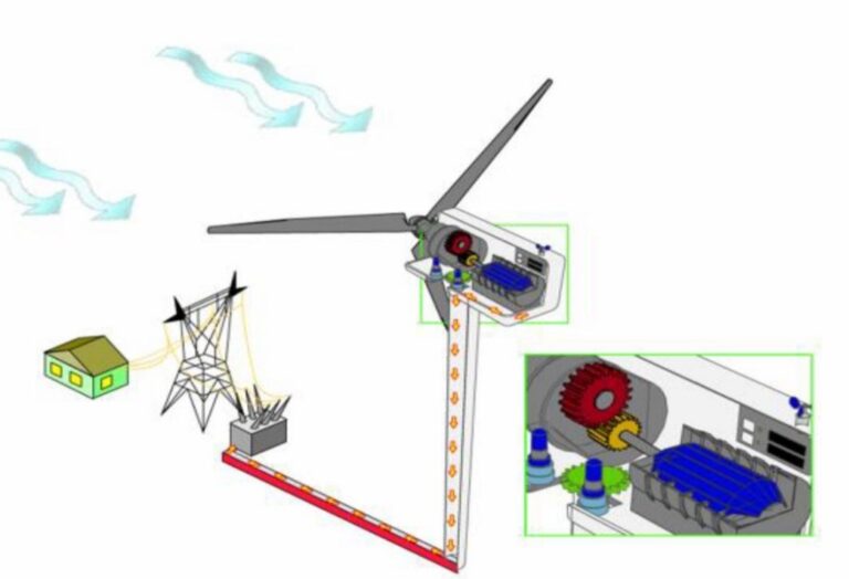
🌬️ Wind Power Plants: 1-5 ohms
🔥 Thermal Power Plants: 0.5-5 ohms
☢️ Nuclear Power Plants: 0.1-1 ohm
📊 Factors Influencing Earthing Resistance:-
✔️ Soil resistivity
✔️ Moisture and temperature
✔️ Electrode material, size, and depth
🔍 Standards to Follow:–
💡 IEEE 80, IEC 60364, ANSI/NFPA 70, BS 7671, and IS 732 provide benchmarks for safe earthing systems.
📐 Testing Methods and Frequency
📏 Methods like Fall-of-Potential, Wenner and Earth Resistance Meter testing ensure accurate measurements.
🕒 Frequency:-
Initial Testing: During commissioning
Routine Testing: Every 6-12 months
Post-Maintenance: As required
Properly maintained earthing systems protect both equipment and personnel.
As electrical engineers, understanding and adhering to these parameters is critical for operational excellence.
