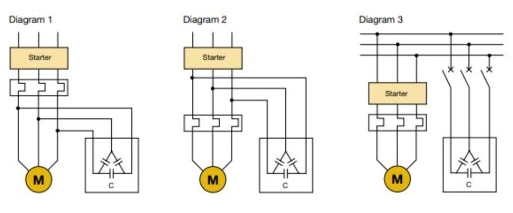
Location of Capacitor Bank for P.F Improvement.
Diagram 1 & 2: –
In this case, the voltage on the load side of the switching and control device is maintained, with the risk of dangerous overvoltages (up to twice the rated voltage value).
Diagram 3: –
The compensation bank is connected only after the motor has been started and disconnected in advance with respect to the switching off of the motor supply.


