Understanding the Key Components of an HVDC Transmission System
In this post, I aim to highlight the key components of an HVDC transmission system.
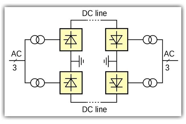
▫️ Converter Stations:-
These are located at both ends of the HVDC transmission line and serve two main roles:
🔹 Rectifier Station: Converts AC power to DC at the sending end.
🔹 Inverter Station: Converts DC power back to AC at the receiving end.
🔹 HVDC systems use 12-pulse bridge converters, created by connecting two 6-pulse bridges in series, for better efficiency and reduced harmonics.
▫️ Converter Transformers
🔹 Step up or step down the voltage levels and provide electrical isolation.
▫️ Harmonic Filters:–
Harmonic distortions from power electronic converters can affect power quality.
To mitigate this, HVDC systems use:
🔹 AC Filters: These are passive circuits used to provide low impedance, shunt paths for AC harmonic currents.
🔹 DC Filters: Divert DC harmonics to earth and prevent their entry into DC lines.
🔹 High-Frequency Filters – The HVDC converter may produce electrical noise in the carrier frequency band from 20 kHz to 490 kHz. High-frequency filters are used to minimize noise and interference with power line carrier communication. Such filters are placed between the converter transformer and the station AC bus.
▫️ Smoothing Reactor
🔹 This is a large inductive reactor, typically oil-filled and cooled.
🔹 It is connected in series with the converter before the DC filter.
🔹 It prevents commutation failures experienced by inverters, reduces harmonics, and avoids breaking off the current.▫️ Reactive Power Sources
🔹 Converters consume reactive power, so shunt capacitors and Static VAR Compensators (SVCs) are used for reactive power compensation, ensuring efficient operation.